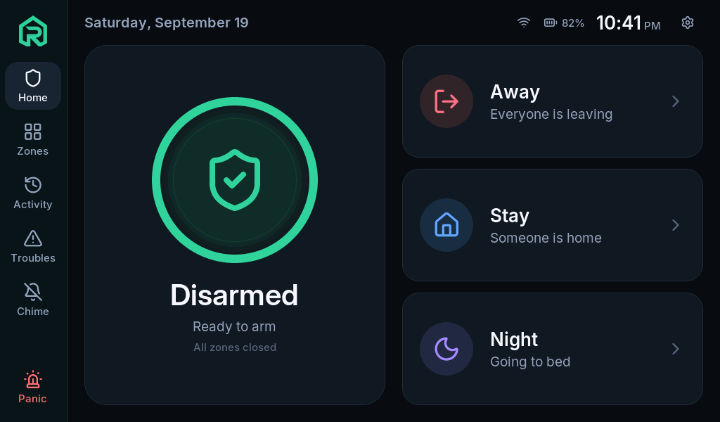
Start with the development panel, then choose how your sensors connect. This guide covers the parts, what building one involves, and the difference between implemented software and hardware that has been tested.
Before you buy
Firmware development is private until the first public release. There is no public panel firmware to install yet. Use this page to plan and check compatibility; RoboAlarms is a DIY software project, and we do not sell hardware or complete alarm kits.
What goes into a build
Parts, software, and time to test.
You’ll assemble and configure your own system. The first release will provide the starting point; this overview helps you plan for it.
Choose the panel and its home.
Plan for the supported touchscreen board, a suitable power supply, and an enclosure or mounting arrangement. Power backup is a separate part of that plan.
Match sensors to their connection.
Check the sensor’s exact protocol and testing status below. Allow for wiring, any required receiver and antenna, and the sensor’s own power. An optional DS3231 backs up the clock only.
Install and configure after release.
Once the public firmware is available, follow the installation guide, configure your users and zones, and set each sensor’s behavior. The documentation is available to explore now.
Test the whole installation.
Check each sensor, alarm action and recovery path in your own setup, including loss of network and power. Project testing complements the checks every installation needs.
01 / The foundation
Current development platform
Elecrow CrowPanel Advanced 7″
The ESP32-P4 version of Elecrow’s 7-inch touchscreen is the board RoboAlarms is being built on. It runs the touchscreen interface and local alarm engine, with an ESP32-C6 providing Wi-Fi connectivity.
Processor
ESP32-P4 + ESP32-C6
Display
7″ · 1024 × 600 · capacitive touch
Tested board revision
PCB revision V1.1
Product family
Elecrow DHE04107D
V1.1 is the board revision we’ve tested with. Supporting other board revisions or screen sizes will require collaboration to adapt the firmware and test it on that hardware. Have a different panel? Help us expand hardware support ↗
The RoboAlarms interface · Example data Software preview, not a hardware product photograph.
Your starting point.
A touchscreen, local processing and Wi-Fi in one development board. Additional sensor hardware depends on the connections you want to explore.
Build out from there
Small modules. More possibilities.
Optional hardware has its own development status. A radio’s frequency or protocol alone doesn’t guarantee that a sensor will work with RoboAlarms.
02 / Radio sensors · Option one
Firmware supported · bench testing pending
CC1101 433 MHz module
A configurable radio option for receiving 433 MHz sensors. The CC1101 connects over SPI, with a separate data line for received pulses. It adds software tuning and signal-strength readings to the receiver setup.
Example module
EBYTE E07-M1101D-SMA
Connection
SPI + GDO0 data line
Power and logic
3.3 V · 433 MHz antenna
Select E07-M1101D-SMA in the linked listing and add a 433 MHz antenna, or choose its antenna bundle. Firmware support is implemented; this module still needs bench validation with RoboAlarms. Sensor compatibility depends on the protocol as well as the frequency.
A receiver from the D-FLIFE 433 MHz transmitter/receiver kit is used on the development panel for RF sensor work. The receiver is the part RoboAlarms uses; the transmitters in the kit aren’t needed for that role.
Documented receiver
RX470-4 / WL101-341 type
Signal
433.92 MHz · ASK/OOK
Listing
D-FLIFE kit · B0BZRRBBNK
Wiring and sensor decoding still need care and testing. The development connection uses 3.3 V power and logic. Check the module supplied by the seller; this is not a promise of compatibility with every 433 MHz sensor.
An optional battery-backed clock that keeps time while the panel is powered off. RoboAlarms detects it automatically, reads the time at startup and keeps it in step with internet time when available. You can also set the time from the panel or Panel Manager.
Example breakout
Adafruit DS3231 · #3013
Connection
I2C · 3.3 V
Backup battery
CR1220 · sold separately
Firmware support is implemented; testing with a fitted module is still pending. The linked Adafruit breakout uses a CR1220 coin cell to power the clock while the panel is off. Connect its power and I2C lines at 3.3 V. The coin cell does not provide backup power for the alarm panel.
Native Zigbee support is part of the RoboAlarms workbench. The selected hardware is Elecrow’s ESP32-H2 wireless module for the CrowPanel Advanced series.
Module
Elecrow ESP32-H2
Store option
Select the ESP32-H2 variant
RoboAlarms support
Not available in firmware yet
The hardware backend and radio testing are still ahead. This link identifies the intended module for development; buying it today won’t add working Zigbee support to RoboAlarms.
Supplier links identify the parts, not a RoboAlarms store. Availability, board revisions and kit contents can change. Hardware notes checked September 2026.
Will my sensors work?
Match the protocol. Check the evidence.
Two sensors can use the same frequency and speak entirely different protocols. This is a development status guide; a verified model-by-model compatibility list is not yet published.
Sensor connections · September 2026 development status
Sensor connection
What you need
Software status
Hardware testing
Wired dry contacts
Suitable contacts wired to the panel’s available inputs.
Implemented. End-of-line resistor supervision is planned.
Input handling runs on the development panel; a real wired-contact acceptance check remains pending.
Sensors shared by Home Assistant
A supported sensor entity, the RoboAlarms integration, and a working local connection to Home Assistant.
Zone sharing is implemented. The sensor still depends on Home Assistant and its own bridge or network.
Pairing and panel status have been tested with real hardware. Shared-sensor zone acceptance remains pending.
In development. Simulator support exists; the hardware backend is not implemented.
No native radio pairing or sensor compatibility has been validated yet.
Other legacy RF sensors
A matching receiver and protocol decoder; no supported build recommendation yet.
Honeywell 5800 / 2GIG (345 MHz), DSC legacy (433 MHz) and Interlogix (319.5 MHz) decoders are future work.
Not currently supported directly. A receiver’s tuning range alone does not add these protocols.
Z-Wave paired directly to the panel
No native Z-Wave radio path is provided.
Direct pairing is not supported. A suitable Home Assistant entity can use the shared-sensor path above.
No direct Z-Wave compatibility claim.
Zigbee and Z-Wave sensors connected through Home Assistant follow the Home Assistant row, not the native radio rows. Many inexpensive fixed-code RF sensors are replayable and do not report regularly enough to reveal a dead battery or lost sensor reliably. Check each model’s behavior as well as its protocol.
Keep exploring
Know the software before you build.
The guides explain how RoboAlarms behaves. The project status page covers testing, remaining work and plans for the first public release.